![]()
Home About Basics Casts Theory Verification
References
Contact
50ft roll-casts
Purposes
The purposes of this section are to show:
·
A roll-cast starting and ending
with the line on water showing the ability to simulate interaction with a water
surface acting as “anchor”.
·
A roll-cast starting and ending
with the line on grass showing the ability to simulate interaction with a grass
surface providing a “poor anchor”.
·
The impact from the water and
grass surfaces on line dynamics and rod dynamics
respectively.
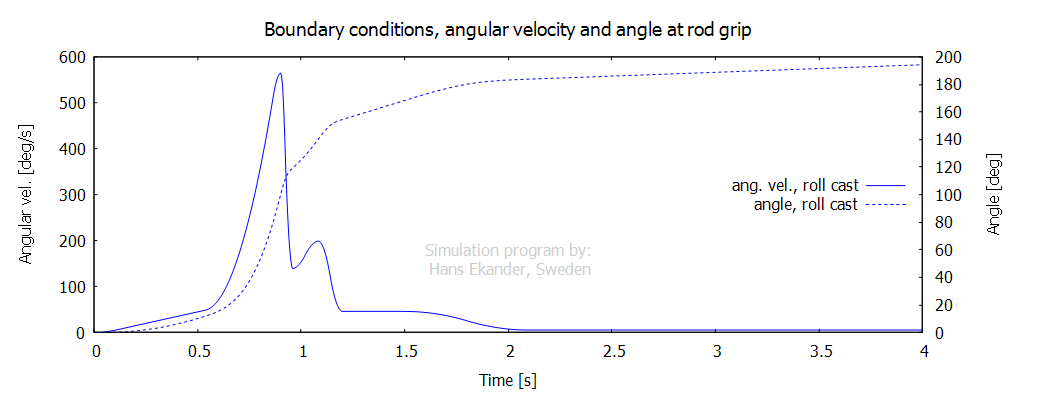
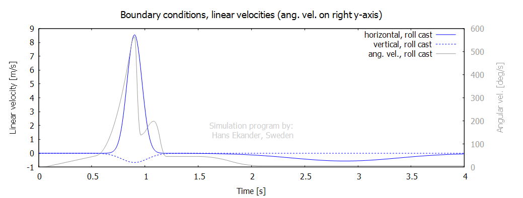
Input, casting strokes
The casting strokes for both casts are
identical. The starting position is with the rod held horizontally behind the
caster. The casting stroke involves angular as well as translational motions
shown in the two graphs below:
Input, equipment
The equipment used is identical to the
equipment used in the 50ft oh ref. cast.
Output, animation
Click on the graph below to start animation.
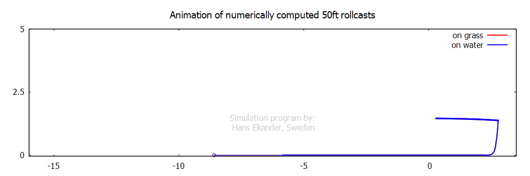
Comments, animation:
·
The animation demonstrates the
capability to simulate interaction of the line with a water surface. The axial
drag on the fly line on the water surface produces what is usually referred to
as an “anchoring effect” i.e., the water drag on the line reduces the
horizontal motion of the line on the water surface during the casting stroke.
·
The animation also demonstrates
the capability to simulate interaction of the line with a grass surface. The
axial force on the fly line on the grass surface is modeled using a friction
coefficient of 0.2. The magnitude of the friction force is independent of the
velocity magnitude and produces a “poor anchor” i.e., the reduction of the
horizontal motion of the line on the grass during the casting stroke by the
friction force is insufficient.
·
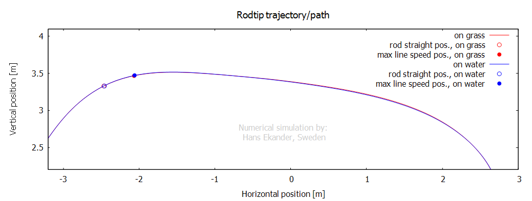
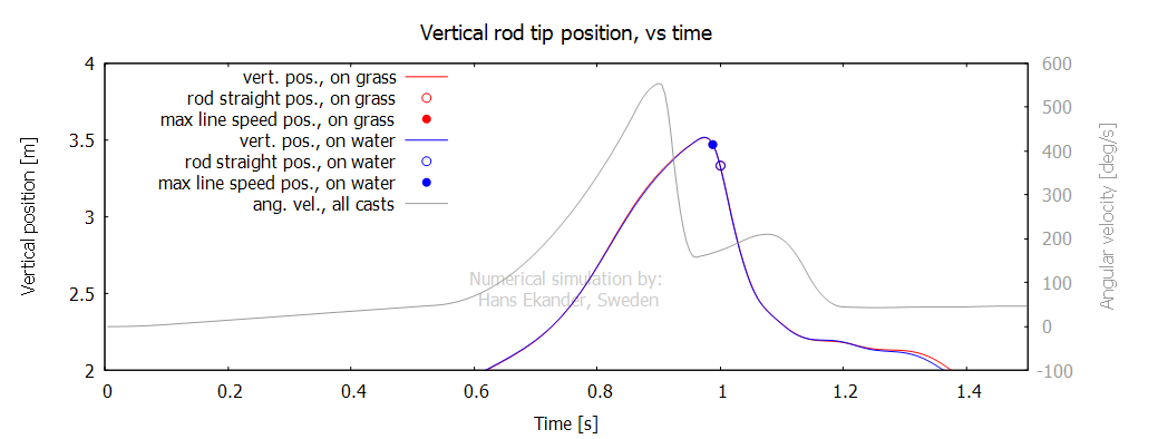
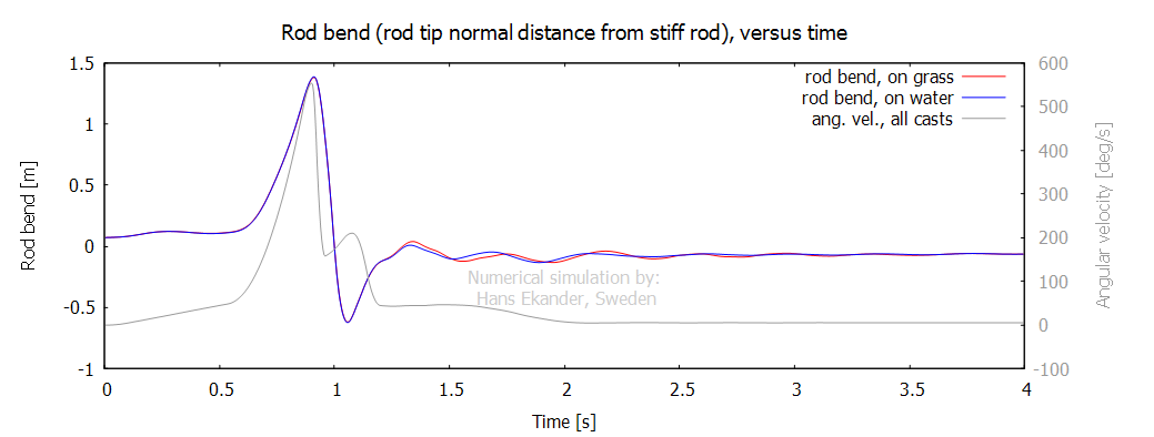
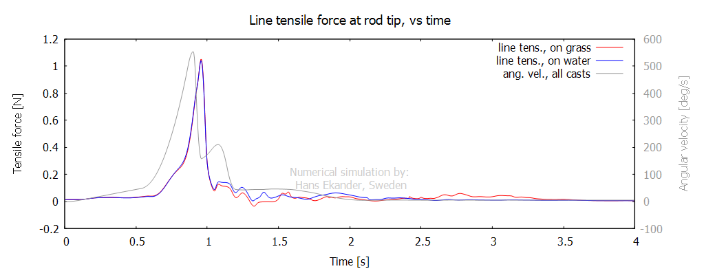
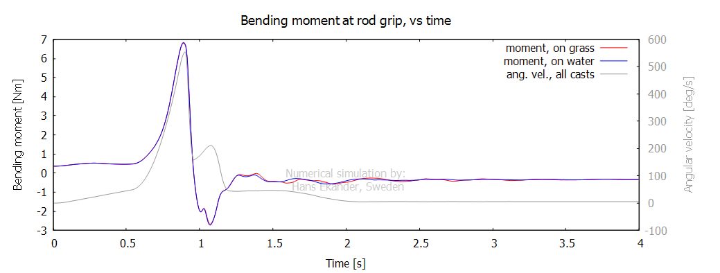
It is noted that the rod movement
during the casting stroke is nearly identical for the two casts. This is also
shown in the graphs below for rod tip trajectories, rod bend and bending
moment. The comparison shows that the difference in “anchor/surface” has a
strong impact on the line dynamics but a very small impact on the rod dynamics.
·
The final line position for the “grass
simulation” is unrealistic. In reality, the line will also move in the 3rd
direction (out of the simulation plane) when landing on the grass. Except for
the final line positioning, the simulation is considered realistic.
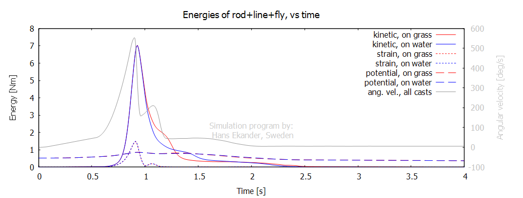
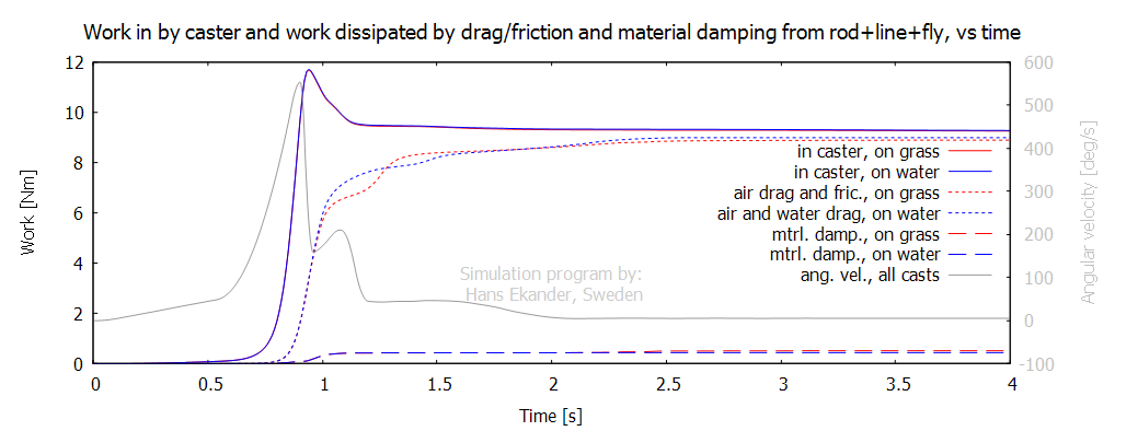
Output, graphs
The graphs below are shown for the time
corresponding to the animation above. For explanations
to the graphs please see the 50ft
oh ref. cast.